MX Series Inverters

Exeltech MX Series Inverters are the world’s first truly redundant, modular inverter system; the most reliable inverter system available. Inverter systems up to 20KW at 120 Vac single phase, 40KW at 240 Vac bi-phase or 60KW at 208 Vac 3 phase are available.
No single malfunction will cause the inverter system to fail. Modules are “hot” insertable. Power levels are expandable, and modules can be added or replaced without interruption to power your critical loads.
The MX system can be configured for power levels from 1 to 20KW with 120 Vac output. Up to 40KW at 240 Vac bi-phase or 60KW at 208 Vac 3 phase with many input and output voltages also available.
A control card and any number of additional 1000 Watt power modules combine to make a standard inverter. This type of system can be expanded as power requirements are increased and upgraded to be N+1 redundant as desired.
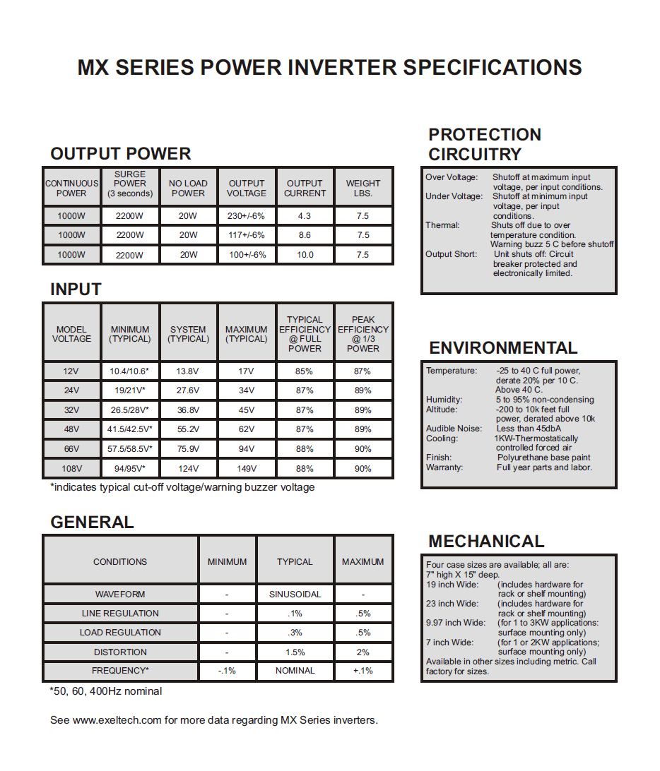
The MX system is extremely compact and lightweight. Power modules weigh only seven pounds each.
Output voltage is precisely regulated, so that no measurable voltage change occurs on the output as input voltage fluctuates. Similarly, less than 0.5 volt change in output voltage will occur when the output load varies from 0 to 100% of rated power. With distortion of 2% maximum, this inverter offers the cleanest sine wave power available.
Models are available that cover all standard battery systems. Custom models can be designed to meet your specific input voltage requirements.
- N+1 Redundant
- Expandable
- Remote Switching
- True Sine Wave
- “HOT” Insertable
- 1000 Watt Modules
- Remote Metering
- Adjustable Power
MX Series Inverter Specifications


MX Series Component Description
The Exeltech MX Series of inverters is a modular system which can be assembled in many combinations to afford the user infinite flexibility. Options such as AC distribution, AC disconnect, metering, DC disconnect, DC distribution, transfer switch and maintenance bypass switch are also available (see accessories below).
The building blocks of the system are as follows:
- Power Modules
- Power Module – A 1000 Watt slave power inverter. It requires drive signals from a Master Module or Control Card as described below. This module is the backbone of the inverter system.
- Master Module – A 1000 Watt power inverter that contains all the electronics necessary to operate; requires an enclosure to provide connections to the battery and AC output. It can also operate up to 19 slave Power Modules. If this module is used, the system cannot be fully redundant.
- Control Card (All MX systems require either a master module or at least one control card.)
- Control Card Phase 1 – Generates the AC voltage and frequency reference necessary to operate up to 20 Power Modules in phase 1. The card itself will not generate any AC output power, nor does any power flow through it. This card can be paralleled with another Control Card to generate a redundant set of reference signals to form the basis of a completely redundant inverter system.
- Control Card Slave Phase – The control cards in phase 2 or phase 3 of a multi-phase system set the AC voltage of their given phase but have no control over the frequency or phase angle relationship with phase 1. Slave phase control cards are designated in the part number by the addition of the “-01” option code.
- Monitoring Modules
- Alarm Card – Can be used in conjunction with a redundant or non-redundant inverter to provide various alarm output signals via LED’s and alarm contact closures. Must be included in redundant systems to detect failure of control card.
- Transfer Switch – Provides the same functions as the alarm card, plus provides a relay to transfer between the inverter and an alternate AC source/utility (40 Amps max output).
- System Monitor I Card – This is a more advanced version of the alarm card that offers few dry contact alarms but adds LCD display and remote monitoring over Ethernet. It also reports AC and DC current and voltage. This card can only be used in single phase systems.
- System Monitor II Card – This is an upgrade from System Monitor I that is compatible with multiphase applications. Sys Mon II also provides remote monitoring via SNMP v1.
- Static Transfer Switch – Available in 5, 10, and 20kW models. The 5kW model offers the same features as the Sys Mon II but provides solid state SCR-based switching with zero transfer time. This switch also adds monitoring of the utility source current and voltage. The 10kW and 20kW models are typically paired with Sys Mon II cards to achieve full functionality.
- Cage Assemblies
- 19″ cage assembly – Compatible with a 19″ relay rack. The smallest cage which can contain a redundant system. Available in the following configurations:
- 19A – Basic configuration for a redundant system. Holds up to 4 Power Modules, 2 Control Cards and either a Transfer Switch, System Monitor Card, or an Alarm Card.
- 19B – Used as an expansion rack or may be used as an expandable, non-redundant inverter, up to 5 KW. (Will not accept X-fer Switch, alarm card, or control cards.)
- 23″ cage assembly – Compatible with a 23″ relay rack.
- 23A – Basic configuration for a redundant system. Holds up to 5 Power Modules, 2 Control Cards and either a Static Transfer Switch, Transfer Switch, System Monitor II, or an Alarm Card.
- 23B – Used as an expansion rack or may be used as an expandable, non redundant inverter, up to 6 KW. (Will not accept X-fer Switch, alarm card, or control cards.)
- 7″ cage assembly – for 1 or 2 KW systems when redundancy is not required.
- 7C – Consists of 1Transfer Switch and 1 Master Module.
- 7B – Expandable up to 2KW. (1 Master Module and 1 Power Module only.)
- 9″ cage assembly – for 1-3KW systems when redundancy is not required.
- 9C – Consists of Transfer Switch, 1 Master Module, and 1 Power Module.
- 9B – Expandable up to 3KW. (1 Master Module and 2 Power Modules only.)
- 19″ cage assembly – Compatible with a 19″ relay rack. The smallest cage which can contain a redundant system. Available in the following configurations:
MX Options
EXELTECH offers many options, such as:
Option (08) Low Idle Current Drain: A ferrite bar across the inductor to aid in reducing power draw when the unit is on but under no load.
Option (07) Conformal Coating: This protects the circuit board in high humidity or airborne contaminant environments.
For details on all available options, please Contact Us.
MX Series Accessories
A/B Buss:
For Redundant DC sources.
Maintenance Bypass Switch:
Allows for complete manual bypass of the inverter for maintenance by connecting the load directly to utility power source.
DC Distribution Panel:
Six breakers rated at 1 Amp up to 30 Amps.
DC Disconnect:
Single DC breaker to disconnect the inverter from the DC input source.
AC Disconnect:
Single breaker to disconnect all loads from the inverter AC output.
AC Distribution Panel:
Up to six breakers rated at 1 Amp up to 30 Amps.
AC Outlet:
6 NEMA receptacles in a 3.2″ x 7” module recommended to be powered through the AC distribution accessory. 8 NEMA receptacles, 1U in height powered through a single circuit breaker.
MX Series System Description
The Exeltech MX Series of inverters is available in three basic architectures; redundant, upgradable, and expandable. Different options and sizes are available to fit varying applications. As a benefit of the MX series modular design, power levels are expandable in any system, as power requirements increase. See MX Product Guide.
1. N+1 Redundant-Expandable Inverter System: For applications where reliability and maintainability are paramount, the N+1 redundant system offers the most cost effective method of achieving redundancy and the ability to maintain the system while loads remain on line. Control cards and power modules (except 12Vdc) are “hot” insertable to allow maintenance without interrupting power to critical loads. Designing the power level with N+1 number of power modules, allows for redundancy without requiring the purchase of a duplicate system. (An A/B Buss option is available, which adds to system reliability).

2. Upgradable Inverter System: The Upgradable system offers the flexibility to add a X-fer switch or alarm card and Full Redundancy for future requirements. A minimum system with as little as one control card and one power module can be upgraded in the future to include additional power modules, X-fer switch or alarm card and an additional control card for full redundancy (see figure II).

3. Expandable Inverter System: This configuration can be used as an independent inverter system (figure III), or to expand power levels of existing MX systems (see stacked systems). By using one master module, a system can be expanded to include a X-fer switch and additional power modules (see figure IV). 1KW inverters with a X-fer switch use the 7″or 9″ (part # 7C, 9C) cage. 1KW, 2KW, and 3KW inverters without an X-fer switch use the 7″ or 9″ (part number 7B, 9B) cage assembly.

MX Series Part Numbering

MX Series Module Part Number

MX Series System Part Number


MX Stacked Rack Numbering System
Data Sheet
MX Series

The Most Trusted Provider
of Inverters Worldwide!
Links
Headquarters
7317 Jack Newell Blvd N
Fort Worth, TX 76118
Phone: 800-886-4683
Phone: 817-595-4969
Fax: 817-595-1290